R2-D2. GERTY 3000. Marvin. K-9. Jinx. These are just a few of the most well-known robotic sidekicks that super geeks like us have come to love over the years. Soon, PLEN2 may join the ranks of these memorable sci-fi characters, with the only difference being actual use in the real world. Whether you’ve ever wanted someone to go to class in your place, to break the ice with an attractive girl at the bar, or to fetch your morning cup ‘o joe, you’re in luck.
Launched on Kickstarter by Japan-based PLEN Project Committee, the 3D-printable, humanoid robotic kit consists of a control board, servo motors and other electronic accessories that allow Makers of all levels to put together themselves. What’s more, you don’t need any technical knowledge or special tools in order to bring your open-source PLEN2 to life.
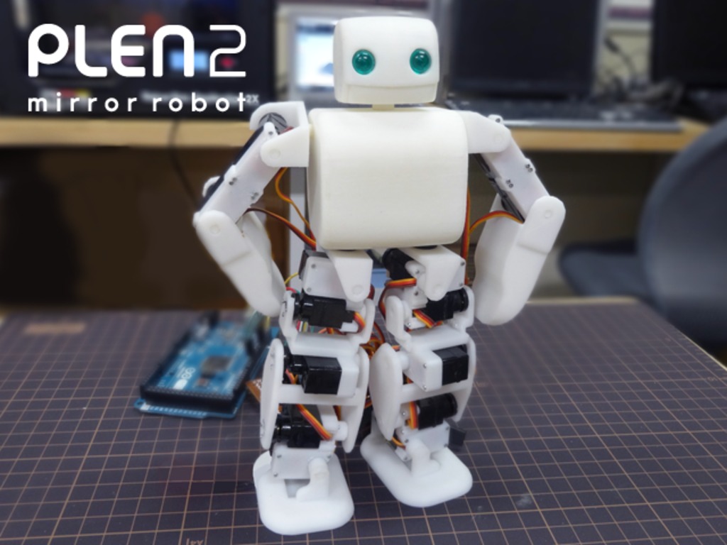
3D data for the main components of the robot are provided free of charge, and with the help of a 3D printer, users can customize the data as well as make their own original parts. Upon completion, the easy-to-manuever and highly-agile humanoid stands approximately 7.87” tall, weighs just over 21 ounces and boasts 18 degrees of freedom. Designed to mirror its human counterpart, PLEN2 aspires to revolutionize the relationship between homo and robo sapiens. To help spur this adoption, the project’s creators have made its kit super simple to assemble, personalize, and of course, use.
The robot’s command center is built around an Arduino Micro (ATmega32U4), and by employing some open-source software, can be programmed to meet any Maker’s wants and needs. PLEN2 is equipped with 24 RC servo motors, 1Mb of on-board EEPROM and an RS-485 communication port in both its control and head board. The head unit also comes standard with a BLE113 Bluetooth Smart module and a six-axis motion sensor, while PWM will drive the LEDs that PLEN2 uses for eyes.
Gadget-lovers can take pleasure in knowing that each PLEN2 can be customized not only in color and design, but in the way that it is controlled as well — this includes by iOS or Android smartphone, facial expression, gestures, myoelectrics and brainwaves, among countless other input methods.
Not only for leisure activities, the humanoid can play an integral role in both educational and medical settings. A wide-range of uses cases include communicating with others in your place, carrying small items around, throwing a pickup game of humanoid soccer, as well as improving medical rehabilitation. What’s more, it can help entice children to pursue STEM disciplines and enable them to experience the joy of making things themselves.
As to whether this project takes off, or if you decide on programming a PLEN2 of your own, one thing is certain: Its theme song will get stuck in your head. Consider yourself warned…
…We told you so. Interested in learning more? Head over to its official Kickstarter page, where its team is currently seeking $40,000. If all goes to plan, you can have can have a PLEN2 alongside of you come November 2015.
With Robotmaster, manufacturers can program robots quickly and efficiently, using industry proven CAD/CAM software technology. Driven by the growing trend towards lean and flexible manufacturing, robots are progressively replacing conventional dedicated manufacturing units, such as CNC milling machines. Robots, once perceived as only positioning devices, have advanced in accuracy and rigidity, and are now being used increasingly for manufacturing and material removal. With industrial robotics, manufacturers are producing higher quality products at lower cost, and are achieving the speed and flexibility they need to challenge their competitors throughout the world.
According to the International Federation of Robotics as of 2013 over 1.5 million robots were estimated to be in operation in industrial applications worldwide, and an additional 160,000 are being sold every year. While many companies currently using CNC machines have been exploring the opportunity of manufacturing with the use of industrial robotics, they have been limited by a lack of time and cost-effective robotic programming tools. Currently less than 1% of robots are programmed using CAD/CAM (computer aided design and manufacturing) software because of a lack of mature robotic programming solutions. Robotmaster eliminates this barrier.
Robotmaster delivers:
Cost-efficiency and flexibility of robots coupled with the ease of programming.
Programming of robots from CAD/CAM software as easy as CNC machine programming.
A sure way to beat the competition -worldwide- on cost, flexibility and response time.
Revolutionary CAD/CAM approach to robot programming software
Our strong background in CAM (Computer Aided Manufacturing) software has enabled us to bring a revolutionary approach to programming for industrial robotics. Unlike the wide range of simulation software packages that claim to be off-line programming for robots while truly only offering very limited programming capability, Robotmaster delivers easy programming of precise tool motion control and quick generation of long tool path trajectories with minimal programmer intervention.
Robotmaster uses mature CAD/CAM software technologies for robotic programming with the same flexibility and speed as software used for programming CNC machine tools. Conventional off-line robot software programming solutions are based on either a very cumbersome and tedious point to point programming approach or a post-processor solution that offers very little flexibility and functionality.
Robotmaster CAD/CAM programming:
Generates more profit with your robot. Robotmaster generates programs off-line and eliminates lost production time during programming.
Delivers closest conformance to design. Robotmaster creates simple or complex robot trajectories accurately without teaching points.
Integrated robot programming software solution
Robotmaster seamlessly integrates programming, simulation and program generation to any CAD/CAM platform. The multi-software approach of conventional off-line robot software solutions forces the use of one software for CAD/CAM programming, another for converting trajectories to robot positions and finally a third to simulate and validate the programmed trajectories.
Robotmaster Integrated Solution
Multi-software Approach
Integrated programming produces:
Quicker robot programming, validation and code generation.
Easy program updates and revisions.
Evolution of robot programming
Using MANUAL TEACH PENDANTS, robots “learn” from the operator jogging the robot through the trajectory and recording points, one point at a time, using the robot’s teach pendant. Robotmaster takes the process off-line and engineers the robot program from the design drawings.
OFF-LINE EMULATORS reproduce the manual teach process in an off-line setting, using a simulation software environment in place of the robot’s teach pendant. Robotmaster follows the path-intensive CAD model accurately and automatically and permits easy updating and revision of the program.
GENERATION 1 OFF-LINE SOFTWARE provides a CAD software environment for manual input of robot parameters for every point of a desired path, one at a time, on a CAD model. Robotmaster automatically generates the full robot trajectory from any CAD/CAM tool path strategy in a fraction of the time.
GENERATION 2 OFF-LINE SOFTWARE generates a robot trajectory by following trajectories drawn manually within a CAD modelling software. Robotmaster automatically generates the full robot trajectory from any CAD/CAM tool path strategy, building direct links between the CAD model and the tool path, without the need to manually draw any additional geometry.
A CAD/CAM POINT CONVERTER is a CAD/CAM post processor, robot simulator utility or standalone software that converts tool path output by CAD/CAM software into a robot trajectory for a specific model or brand of robot. Robotmaster is a fully integrated solution that permits seamless interaction between CAD/CAM and robot programming functionality, allowing trajectory optimization and integrated robot kinematics and simulation for a wide portfolio of robot models and brands.
Solving programming challenges
Struggling to program a robot the way you do a CNC machine tool? Robotmaster is up to the challenge:
Not easy to check intuitively robot joint limits and robot-to-part collisions?
Robotmaster automatically checks programs for joint limits, robot reach limitations and collisions.
Need to do manual touch-up and rework of your off-line programmed points?
Robotmaster inherently calculates robot joint values and properly sets parameters to give seamless program playback without manual intervention.
CAD/CAM data is not enough to provide position and orientation data for a 6-axis robot?
Robotmaster uses automated settings for orienting the robot tool to manage trajectories with complex orientation changes.
Your program produces errors and stops running when it passes through one of your robot’s singularity zones?
Robotmaster checks for singularity and has powerful tools to correct programs containing singularities.
How to select from the up to 8 possible configurations that your robot has to achieve everyone of its programmed points?
Robotmaster can vary configurations for optimal programming of trajectories or follow your specific robot configuration choice.
Inaccuracies in your part or tool setup cause production delays as you make manual adjustments?
Robotmaster eliminates adjustments and increases program accuracy by calibrating the physical part and tool setup with the virtual CAD model.
REFERENCE
Billard-handbook
We are indebted to them and the sharing is non commercial
Remote Control Robotics
Some may argue that a robot is not really a robot if it isnt autonomous. Maybe it is or maybe it isn’t. Point being, those some are morons. Learning how to implement remote control features into a robot is a very important skill in robot making. To justify it, I will quickly go over robot intelligent control methods . . .
Introductory to Robot Intelligence
There is actually a spectrum for robot intelligence. Fully remote control and fully autonomous are not your only options. Instead you should decide what level of intelligence you wish your robot to have. Generally assume the more intelligent, the more difficult to build.
Here are the main categories:
Automaton ‘Intelligence’
The lowest level of robot ‘intelligence’ is a simple automaton device. My definition of an automaton is a device where there is absolutely zero decisions made no matter the given environment. They are simple devices where the action it does is repetitive and automatic. A simple circuit with a motor or a combination of gears and a spring could easily be an automaton. Ever hear of those ‘robots’ from the 1800’s that apparently can write names and poems and other useless stuff? They were very well designed gear integrations. However these ‘robots’ would keep writing even if the ink well ran out of ink . . . The device simply has no fault tolerance, and will continue attempting the action. They did not even have a method to sense the environment – a requirement of decision making. BEAM ‘robots’ basically fall into the same category, except they are made from very well designed electronics instead of gears.
Remote Control ‘Intelligence’
Remote control is the next level of robot ‘intelligence.’ Our current technology is capable of building so many machines physically capable of so much more than any lifeform on our planet. Our planes fly many times the speed of sound, our everyday cars can cross the Sahara Desert in days, but our best computers cannot even match a roach brain in terms of autonomy. Solution? Put the human brain in the driving seat of our machines. This allows for the best of both worlds. Strength and expendability of a machine, brain of a human. Battlebots is a perfect example.
Teleoperation
Teleoperation is one step above remote control. The advantage a computer has over the human brain is speed. A typical home computer today can crunch more numbers in a few seconds than a human can in an entire lifetime. But despite that speed, the computer does not have a good understanding of the situation. Added to that, our most advanced electronic sensors cannot match our human eyes and ears for observing the situation. Solution? Let the human make the decisions, but have the computer carry them out. A perfect use for this would be a robot spider. A human operator in no way can control 8 legs with 3 joints each. Instead, the human would give commands like ‘go forward’ or ‘rotate’ and the computer will handle the rest. This method is also very common with space robots because of the long transmission delay.
Full Autonomy
Fully autonomous robots are still a dream. It is a huge area in current state-of-the-art robotics research. It concerns artificial intelligence, consciousness, advanced sensory percerption . . . the list goes on. Huge philosphical implications as well. But all this is out of the scope of this tutorial. If you make a robot that can intentionally navigate from your couch to your kitchen and back without any collisions all by itself, you have built an autonomous robot. But if it fails to bring a beer back you are still a beginner in my eyes . . .
How to Build a Remote Control Robot
The remote control robot is probably the easiest of all robots you can make. A complete beginner can probably make a basic remote control robot in under an hour. The electronics part is plug-n-play, the robot chassis being what will take a little time. Remote control robotics is great for those who want to build a robot – yet does not have enough time, skill, and/or patience to so see a large project through to completion. Have a look at an example of a wall climbing robot with an arm.
First, a video to help you get started:
All you need is a few cheap commercially available items:
Remote Control Transmitter
The remote control transmitter is the handheld thingy with knobs and buttons and a long intenna sticking out of it. This will be the most expensive part you need to buy, around $40-$200. It will require it’s own battery and battery charger. The remote control transmitter usually has very good range. Once as a test, I put my robot in the basement of a building, climbed to floor 10, then operated it without any issues. If you plan to ever do USAR (Urban Search and Rescue), this is a useful feature. The most important feature you need to be concerned with is number of channels it can operate on. Each channel allows you to control one more item on your robot. I recommend at least three, but I have often used up to six on a single robot in the past.
Receiver
The receiver is a small little box thingy that you put on your robot. It accepts the signal from your transmitter, processes it, then outputs a servo ready signal. This will be the second most expensive part, usually around $30-$60. It will require around ~5V to power it.
Receivers can get really small:
If you want to use a higher voltage for the servos, get something called a Y-harness (see below image).
You simply attach it to a servo port, and then attach your higher voltage batteries and your servo to the other end. Read the instructions for power! Like with the transmitter, you must be concerned with how many channels you would like to have.
Operating Frequency Crystal
Both your transmitter and your receiver will each require a crystal. These are necessary to ensure both of your devices are operating under the same frequency (so purchase both crystals with the samechannel!!!). For RC, there are two frequencies you need to be aware of. One is for air and one is for surface. Remember, its illegal and bad practice to control a remote control car with an air frequency. You could accidently cause someone’s remote control aircraft to crash and kill some poor cute innocent squirrel! But you already knew that . . . When you purchase your receiver/transmitter, they will specify whether it should be used for air or surface RC. Another note, the crystal is fragile. If your remote control vehicle crashes a lot, the crystal could get damaged. I once made a robot for a USAR competition that was designed to handle 7 foot drops. But apparently the crystal was not. It broke. Sadness. The solution? Receivers often come with a foam padthingy to wrap it in for shock absorption. If not, find some foam padding and use it. The crystals usually come as part of your transmitter and receiver, but if not, or if you break one, they cost like $8 plus shipping to replace.
The materials above are the basics required for remote control, but you are not yet done. You now need a few more things to build the robot chassis:
Optional: Robot Frame Material
HDPE
and/or
aluminum
should be used for the frame. Want to build it in 5 minutes? A simple square sheet of HDPE with
all
parts velcroed on will actually work! But you should attach everything more permanantly for a well designed robot.
Optional: Servos
Servos, although not required, are designed to be used with remote control vehicles. All you do is literally plug it straight into your receiver and it instantly works. Get two servos – one for each side of your robot – so that you have differential drive. Put a castor in back for balance. You can also use additional servos for other things such rotating a camera, lifting a shovel, or operating a robot arm. If you are on a strict budget, I highly recommend the Hitec HS-311 servos. They only cost about $8 and work really well for what you need. But of course, the $30 servos work even better . . . And here is how to mount servos onto a robot chassis.
Optional: Teleoperation
Now you do not need a microcontroller for any basic remote controlled robot. But if you want it teleoperational, you must have something to process your commands. So how does this work? The basic concept is
– send a command with the transmitter to the receiver
the receiver then outputs a servo square wave
a simple resistor capacitor circuit changes this square wave to an analog value
and then an analog port on your microcontroller interprets this analog value into a particular command, based upon your written program.
The servo signal to analog signal converter circuit:
Optional: High Power Motor Driver / Speed Controller
If you want a high powered robot that uses something much more powerful than hobby servos, you would instead want a motor driver. Most on the market should directly accept a signal made for a servo, and convert that to what you would need for DC motors. Just hook this device up to your receiver, and attach your motors and battery to it, and by happy squirrels you have an instant Battlebot. Be aware that these can get a little expensive, and many are only capable of handling a single motor – meaning you would need to buy two.
Optional: Speed Controller
The speed controller is basically an H-bridge that operates by a remote control signal. Plug one wire into the receiver, two onto the battery leads, and two on the motor leads – and wallah its controllable by your transmitter. If you wanted to build a fast dc motor driven remote control vehicle, or perhaps need a motor to drive the weapon of your battle bot, this is the way to go.
Last Step: Assembly of your Remote Control Robot
I figure the best way to explain this is to show an example. This particular robot was made by me and a friend in less than 5 hours back in early 2003. It uses somewhat expensive lexan plates, a lego castor, and super glue, double sided sticky tape, and velcro to connect everything together. Ghetto, yes. But it held together really well and was easy/quick to make.
It was designed to play soccer, but since I lived in Pittsburgh at the time there was also plenty of snow to shovel . . . Here is a video of it in action:
And here are two teams of remote controlled
soccer robots all made in the same fasion:
Radio Frequency Reference Chart
On rare occasions you may want to know what frequency you are broadcasting on, and not just which channel it is. For example, if your remote control robot is for an underwater environment, you would want the lowest frequency possible to minimize attenuation (interference).
72 megahertz, Channels 11 – 60: This is the most popular choice for flying models. Most radios designed for model aircraft and helicopters will be available on these channels. DO NOT use this frequency for anything other than aircraft, as you could unintentionally cause a crash of someone else’s remote control aircraft nearby. Big deal? Not so big when they lose hundreds in $$ from damage, or even worse, a death or injury results from the crash . . .
75 megahertz, Channels 61-90: Cars, boats, and other non-flying models must use one of these channels. Pistol grip radios are available on 27 MHz as well as 75.
27 megahertz, Channels A1-A6 and 50 megahertz, Channels 00-09: While legal for air or surface use, we recommend that 27MHz be used only for surface models. A pilot and driver broadcasting on the same 27MHz frequency would cause interference and could cause a crash. 50MHz channels can be used for R/C, but require the user to attain a Technician-class Amateur Radio License from the FCC.
find Smart IR Remote apk on Internet free or you can download full version from Blackmart .
This app is control any type remote control Device like TV,A.C.,DVD,Set Top Box,Fan ya any type of device which can controllable by Remote Control.
This app can make clone of remote control of Devices.This is a good app for those people which have lots of remote control in his house.This is also for hacking fans,tv,and other consoles.
Smart IR Remote is the only IR remote universal app for Android that you’ll ever need: it’s smart, with a device coverage that is huge (700000 devices, with more added daily and on request), and it’s the only one that makes use of features only your phone/tablet have, that a plastic remote (like the Logitech Harmony) never will. As IR remote controls go, especially android remote controls, you’ll never find one better!
Smart Remote works with any Samsung, HTC and Medion Lifetab devices with an InfraRed Blaster, and most other brand phone/tablet with an IR Blaster that runs Android 4.4 or above provided originally by the manufacturer. Even better, Smart IR Remote also works on most custom ROMs like CyanogenMod.
Smart IR Remote is an universal smart remote control app that can command almost anything that receives InfraRed commands, like a TV, Set Top Box (cable and satellite box), DVD, BluRay player, VCR, Amplifier, Air Conditioner, AV Receiver, DSLR camera, etc. Better yet, you can combine your remotes into smart remotes (activities) so that on your custom remote you’ll have the volume buttons to your surround system, the channel buttons to control your set top box and the display buttons to control your TV. It’s the only Android universal tv remote that can do that, while controlling any other device too!
Extra Features from Smart IR Remote
AIR GESTURES – exclusive to Android 4.1-4.4 Galaxy S4
Simply wave your hand above your phone to change channels, volume, or whatever your heart pleases – it’s all configurable! MUTE/PAUSE ON PHONE CALL
Smart Remote can now mute your TV, pause your media player, or even switch them off if you wish, all of that when your phone rings. MACROS
Group commands in batches, sort them and add delays, and then execute the series of commands one after the other. Imagine being able to turn your TV, Xbox and surround system on, switch TV to HDMI 1 all with a single tap! AUTOMATED TASKS
Automatically execute commands or macros, when certain conditions occur: your phone rings, at a time chosen by you, when you use your phone’s Volume Buttons. Are you a Tasker fan? We have a Tasker plugin that integrates well and lets you to send commands WIDGETS
With both lockscreen and homescreen widgets, you’ll have your favorite just a tap away when you grab your phone. Need something even better? read on FLOATING REMOTE (CHATHEAD)
The floating remote is a remote that stays above other apps which can be shown with just a single tap and lets you send commands even while you’re playing a game on your phone BACKUP / RESTORE
If you switch ROMs often or need the remotes you put hard work on to be available on all your devices, you can simply make a backup once and then restore on all your other devices RECORD REMOTES – exclusive to the HTC One due to hardware limitations in other devices
Couldn’t find your remote in our list? Simply record each button to have it just the way you want it. Opt in to share your remote so that other customers can make use of your work too!
Almost all brands in the world are supported, including Samsung, Sony, Toshiba, Panasonic, Yamaha, DirecTV (Direct TV), etc. You can find Smart IR Remote apk on Internet free.
Heartiest Gratitute for sharing copyright with us Mr.Alok Rathaur
Researchers from KTH Royal Institute of Technology are working on electronics able to handle the extremely high temperatures of Venus. The electronics are based on silicon carbide, a semiconductor that can withstand the extremely harsh climate of the second planet from the sun.
“There are some places in space where the temperature is very high, such as the surface of Venus, where the temperature is 460 degrees Celsius,” says Carl Mikael Zetterling, professor of solid state electronics at KTH, and one of the researchers on the project. “But there are also places around the moons of Jupiter and Mercury, where the environments are really tough and where a powerful semiconductor such as silicon carbide can also be used.”
The space researchers, who may use the new Venus landsailing rover robot, want to find out is how the climate works on Venus, which in turn may provide explanations for the Earth’s climate. But Zetterling says there is one more point to take into consideration with silicon carbide in space research. Major space missions have proven fruitful for microelectronics.
“You could say that microelectronics has much to thank NASA and the Apollo projects for. These were some of the first customers to use silicon in integrated circuits. It is something that helped to get this industry going,” he says.
Zetterling believes that this focus on electronics for a new Venus lander robot will give a boost to the silicon carbide ahead. He notes that it is difficult to obtain funds for research in microelectronics. But demonstrating the technique on Venus increases the possibilities to show silicon carbide’s potential.
“The Knut and Alice Wallenberg Foundation, which funds the project, wish to see something that really makes an impression, something that makes an impact. And to show something that works on Venus certainly meets that objective. But I see applications on Earth as being much more important,” he says.
The Venus project would be the first time that silicon carbide is used in a high temperature application. However, the material has been used in high-voltage applications for at least a decade, such as for the conversion of solar energy into electrical energy.
Credit and we pay tribute to professor R Kremen For sharing editorial and copyright
Google Fiber is a new fiber-optic internet and television service from Google offered in select cities that provides up to 1Gbps internet speeds (both upload and download). According to Google, the Gigabit internet speeds are up to 100 times faster than the average broadband speeds in place today.
Google Fiber made its public debut in Kansas City in September 2012, and expansion plans are in place for Austin, Texas and Provo, Utah, as well as additional cities in the future. The Google Fiber service is available for $120 per month for the combined internet and television services, or $70 per month for just the internet service. A free Google Fiber internet service option is also available that offers speeds of up to 5Mbps for a one-time “construction fee” of $300.
Google Fiber subscribers are provided with a Network box with 4 Gigabit Ethernet ports, a DVR Storage box with 2TB of data storage that can record up to eight live television shows simultaneously, TV boxes for each TV or HDTV to be used with the service, and a Google Nexus 7 tablet device that can be used as both a viewing device and a remote control for Google Fiber. In addition to the included 2TB storage box, Google Fiber customers are also provided with 1TB of cloud storage via Google Drive.
, also called photovoltaic cell, any device that directly converts the energy in light into electrical energy through the photovoltaic effect. The overwhelming majority of solar cells are fabricated from silicon—with increasing efficiency and lowering cost as the materials range from amorphous (noncrystalline) to polycrystalline to crystalline (single crystal) silicon forms. Unlike batteries or fuel cells, solar cells do not utilize chemical reactions or require fuel to produce electric power, and, unlike electric generators, they do not have any moving parts.
Solar cells can be arranged into large groupings called arrays. These arrays, composed of many thousands of individual cells, can function as central electric power stations, converting sunlight into electrical energy for distribution to industrial, commercial, and residential users. Solar cells in much smaller configurations, commonly referred to as solar cell panels or simply solar panels, have been installed by homeowners on their rooftops to replace or augment their conventional electric supply. Solar cell panels also are used to provide electric power in many remote terrestrial locations where conventional electric power sources are either unavailable or prohibitively expensive to install. Because they have no moving parts that could need maintenance or fuels that would require replenishment, solar cells provide power for most space installations, from communications and weather satellites to space stations. (Solar power is insufficient for space probes sent to the outer planets of the solar system or into interstellar space, however, because of the diffusion of radiant energy with distance from the Sun.) Another growing application of solar cells is in consumer products, such as electronic toys, handheld calculators, and portable radios. Solar cells used in devices of this kind may utilize artificial light (e.g., from incandescent and fluorescent lamps) as well as sunlight.
While total photovoltaic energy production is minuscule, it is likely to increase as fossil fuel resources shrink. In fact, the world’s current energy consumption could be supplied by covering less than 1 percent of the Earth’s surface with solar panels. The material requirements would be enormous but feasible, as silicon is the second most abundant element in the Earth’s crust. These factors have led solar proponents to envision a future “solar economy” in which practically all of humanity’s energy requirements are satisfied by cheap, clean, renewable sunlight.
Solar cell structure and operation
Solar cells, whether used in a central power station, a satellite, or a calculator, have the same basic structure, as shown in the figure. Light enters the device through an optical coating, or antireflection layer, that minimizes the loss of light by reflection; it effectively traps the light falling on the solar cell by promoting its transmission to the energy-conversion layers below. The antireflection layer is typically an oxide of silicon, tantalum, or titanium that is formed on the cell surface by spin-coating or a vacuum deposition technique.
The three energy-conversion layers below the antireflection layer are the top junction layer, the absorber layer, which constitutes the core of the device, and the back junction layer. Two additional electrical contact layers are needed to carry the electric current out to an external load and back into the cell, thus completing an electric circuit. The electrical contact layer on the face of the cell where light enters is generally present in some grid pattern and is composed of a good conductor such as a metal. Since metal blocks light, the grid lines are as thin and widely spaced as is possible without impairing collection of the current produced by the cell. The back electrical contact layer has no such diametrically opposed restrictions. It need simply function as an electrical contact and thus covers the entire back surface of the cell structure. Because the back layer also must be a very good electrical conductor, it is always made of metal.
Since most of the energy in sunlight and artificial light is in the visible range of electromagnetic radiation, a solar cell absorber should be efficient in absorbing radiation at those wavelengths. Materials that strongly absorb visible radiation belong to a class of substances known as semiconductors. Semiconductors in thicknesses of about one-hundredth of a centimetre or less can absorb all incident visible light; since the junction-forming and contact layers are much thinner, the thickness of a solar cell is essentially that of the absorber. Examples of semiconductor materials employed in solar cells include silicon, gallium arsenide, indium phosphide, and copper indium selenide.
When light falls on a solar cell, electrons in the absorber layer are excited from a lower-energy “ground state,” in which they are bound to specific atoms in the solid, to a higher “excited state,” in which they can move through the solid. In the absence of the junction-forming layers, these “ free” electrons are in random motion, and so there can be no oriented direct current. The addition of junction-forming layers, however, induces a built-in electric field that produces the photovoltaic effect. In effect, the electric field gives a collective motion to the electrons that flow past the electrical contact layers into an external circuit where they can do useful work.
The materials used for the two junction-forming layers must be dissimilar to the absorber in order to produce the built-in electric field and to carry the electric current. Hence, these may be different semiconductors (or the same semiconductor with different types of conduction), or they may be a metal and a semiconductor. The materials used to construct the various layers of solar cells are essentially the same as those used to produce the diodes and transistors of solid-state electronics and microelectronics . Solar cells and microelectronic devices share the same basic technology. In solar cell fabrication, however, one seeks to construct a large-area device because the power produced is proportional to the illuminated area. In microelectronics the goal is, of course, to construct electronic components of ever smaller dimensions in order to increase their density and operating speed within semiconductor chips, or integrated circuits.
The photovoltaic process bears certain similarities to photosynthesis, the process by which the energy in light is converted into chemical energy in plants. Since solar cells obviously cannot produce electric power in the dark, part of the energy they develop under light is stored, in many applications, for use when light is not available. One common means of storing this electrical energy is by charging electrochemical storage batteries. This sequence of converting the energy in light into the energy of excited electrons and then into stored chemical energy is strikingly similar to the process of photosynthesis.
Solar panel design
Most solar cells are a few square centimetres in area and protected from the environment by a thin coating of glass or transparent plastic . Because a typical 10 cm × 10 cm (4 inch × 4 inch) solar cell generates only about two watts of electrical power (15 to 20 percent of the energy of light incident on their surface), cells are usually combined in series to boost the voltage or in parallel to increase the current. A solar, or photovoltaic (PV), module generally consists of 36 interconnected cells laminated to glass within an aluminum frame. In turn, one or more of these modules may be wired and framed together to form a solar panel. Solar panels are slightly less efficient at energy conversion per surface area than individual cells, because of inevitable inactive areas in the assembly and cell-to-cell variations in performance. The back of each solar panel is equipped with standardized sockets so that its output can be combined with other solar panels to form a solar array. A complete photovoltaic system may consist of many solar panels, a power system for accommodating different electrical loads, an external circuit, and storage batteries. Photovoltaic systems are broadly classifiable as either stand-alone or grid-connected systems.
Stand-alone systems contain a solar array and a bank of batteries directly wired to an application or load circuit. A battery system is essential to compensate for the absence of any electrical output from the cells at night or in overcast conditions; this adds considerably to the overall cost. Each battery stores direct current (DC) electricity at a fixed voltage determined by the panel specifications, although load requirements may differ. DC-to-DC converters are used to provide the voltage levels demanded by DC loads, and DC-to-AC inverters supply power to alternating current (AC) loads. Stand-alone systems are ideally suited for remote installations where linking to a central power station is prohibitively expensive. Examples include pumping water for feedstock and providing electric power to lighthouses, telecommunications repeater stations, and mountain lodges.
Grid-connected systems integrate solar arrays with public utility power grids in two ways. One-way systems are used by utilities to supplement power grids during midday peak usage. Bidirectional systems are used by companies and individuals to supply some or all of their power needs, with any excess power fed back into a utility power grid. A major advantage of grid-connected systems is that no storage batteries are needed. The corresponding reduction in capital and maintenance costs is offset, however, by the increased complexity of the system. Inverters and additional protective gear are needed to interface low-voltage DC output from the solar array with a high-voltage AC power grid. Additionally, rate structures for reverse metering are necessary when residential and industrial solar systems feed energy back into a utility grid.
The simplest deployment of solar panels is on a tilted support frame or rack known as a fixed mount. For maximum efficiency, a fixed mount should face south in the Northern Hemisphere or north in the Southern Hemisphere, and it should have a tilt angle from horizontal of about 15 degrees less than the local latitude in summer and 25 degrees more than the local latitude in winter. More complicated deployments involve motor-driven tracking systems that continually reorient the panels to follow the daily and seasonal movements of the Sun. Such systems are justified only for large-scale utility generation using high-efficiency concentrator solar cells with lenses or parabolic mirrors that can intensify solar radiation a hundredfold or more.
Although sunlight is free, the cost of materials and available space must be considered in designing a solar system; less-efficient solar panels imply more panels, occupying more space, in order to produce the same amount of electricity. Compromises between cost of materials and efficiency are particularly evident for space-based solar systems. Panels used on satellites have to be extra-rugged, reliable, and resistant to radiation damage encountered in the Earth’s upper atmosphere. In addition, minimizing the liftoff weight of these panels is more critical than fabrication costs. Another factor in solar panel design is the ability to fabricate cells in “thin-film” form on a variety of substrates, such as glass, ceramic, and plastic, for more flexible deployment. Amorphous silicon is very attractive from this viewpoint. In particular, amorphous silicon-coated roof tiles and other photovoltaic materials have been introduced in architectural design and for recreational vehicles, boats, and automobiles.
Development of solar cells
The development of solar cell technology stems from the work of the French physicist Antoine-César Becquerel in 1839. Becquerel discovered the photovoltaic effect while experimenting with a solid electrode in an electrolyte solution; he observed that voltage developed when light fell upon the electrode. About 50 years later, Charles Fritts constructed the first true solar cells using junctions formed by coating the semiconductor selenium with an ultrathin, nearly transparent layer of gold. Fritts’s devices were very inefficient converters of energy; they transformed less than 1 percent of absorbed light energy into electrical energy. Though inefficient by today’s standards, these early solar cells fostered among some a vision of abundant, clean power. In 1891 R. Appleyard wrote of
the blessed vision of the Sun, no longer pouring his energies unrequited into space, but by means of photo-electric cells…, these powers gathered into electrical storehouses to the total extinction of steam engines, and the utter repression of smoke.
By 1927 another metal-semiconductor-junction solar cell, in this case made of copper and the semiconductor copper oxide, had been demonstrated. By the 1930s both the selenium cell and the copper oxide cell were being employed in light-sensitive devices, such as photometers, for use in photography. These early solar cells, however, still had energy-conversion efficiencies of less than 1 percent. This impasse was finally overcome with the development of the silicon solar cell by Russell Ohl in 1941. Thirteen years later, aided by the rapid commercialization of silicon technology needed to fabricate the transistor, three other American researchers—Gerald Pearson, Daryl Chapin, and Calvin Fuller—demonstrated a silicon solar cell capable of a 6 percent energy-conversion efficiency when used in direct sunlight. By the late 1980s silicon cells, as well as cells made of gallium arsenide, with efficiencies of more than 20 percent had been fabricated. In 1989 a concentrator solar cell in which sunlight was concentrated onto the cell surface by means of lenses achieved an efficiency of 37 percent owing to the increased intensity of the collected energy. By connecting cells of different semiconductors optically and electrically in series, even higher efficiencies are possible, but at increased cost and added complexity. In general, solar cells of widely varying efficiencies and cost are now available.
In electronics, a semiconductor device that emits infrared or visible light when charged with an electric current. Visible LEDs are used in many electronic devices as indicator lamps, in automobiles as rear-window and brake lights, and on billboards and signs as alphanumeric displays or even full-colour posters. Infrared LEDs are employed in autofocus cameras and television remote controls and also as light sources in fibre-optic telecommunication systems.
The familiar lightbulb gives off light through incandescence, a phenomenon in which the heating of a wire filament by an electric current causes the wire to emit photons, the basic energy packets of light. LEDs operate by electroluminescence, a phenomenon in which the emission of photons is caused by electronic excitation of a material. The material used most often in LEDs is gallium arsenide, though there are many variations on this basic compound, such as aluminum gallium arsenide or aluminum gallium indium phosphide. These compounds are members of the so-called III-V group of semiconductors—that is, compounds made of elements listed in columns III and V of the periodic table. By varying the precise composition of the semiconductor, the wavelength (and therefore the colour) of the emitted light can be changed. LED emission is generally in the visible part of the spectrum (i.e., with wavelengths from 0.4 to 0.7 micrometre) or in the near infrared (with wavelengths between 0.7 and 2.0 micrometres). The brightness of the light observed from an LED depends on the power emitted by the LED and on the relative sensitivity of the eye at the emitted wavelength. Maximum sensitivity occurs at 0.555 micrometre, which is in the yellow-orange and green region. The applied voltage in most LEDs is quite low, in the region of 2.0 volts; the current depends on the application and ranges from a few milliamperes to several hundred milliamperes.
The term diode refers to the twin-terminal structure of the light-emitting device. In a flashlight, for example, a wire filament is connected to a battery through two terminals, one (the anode) bearing the negative electric charge and the other (the cathode) bearing the positive charge. In LEDs, as in other semiconductor devices such as transistors, the “terminals” are actually two semiconductor materials of different composition and electronic properties brought together to form a junction. In one material (the negative, or n-type, semiconductor) the charge carriers are electrons, and in the other (the positive, or p-type, semiconductor) the charge carriers are “holes” created by the absence of electrons. Under the influence of an electric field (supplied by a battery, for instance, when the LED is switched on), current can be made to flow across the p–n junction, providing the electronic excitation that causes the material to luminesce.
In a typical LED structure, the clear epoxy dome serves as a structural element to hold the lead frame together, as a lens to focus the light, and as a refractive index match to permit more light to escape from the LED chip. The chip, typically 250 × 250 × 250 micrometres in dimension, is mounted in a reflecting cup formed in the lead frame. The p–n-type GaP:N layers represent nitrogen added to gallium phosphide to give green emission; the p–n-type GaAsP:N layers represent nitrogen added to gallium arsenide phosphide to give orange and yellow emission; and the p-type GaP:Zn,O layer represents zinc and oxygen added to gallium phosphide to give red emission. Two further enhancements, developed in the 1990s, are LEDs based on aluminum gallium indium phosphide, which emit light efficiently from green to red-orange, and also blue-emitting LEDs based on silicon carbide or gallium nitride. Blue LEDs can be combined on a cluster with other LEDs to give all colours, including white, for full-colour moving displays.
Any LED can be used as a light source for a short-range fibre-optic transmission system—that is, over a distance of less than 100 metres (330 feet). For long-range fibre optics, however, the emission properties of the light source are selected to match the transmission properties of the optical fibre, and in this case the infrared LEDs are a better match than the visible-light LEDs. Glass optical fibres suffer their lowest transmission losses in the infrared region at wavelengths of 1.3 and 1.55 micrometres. To match these transmission properties, LEDs are employed that are made of gallium indium arsenide phosphide layered on a substrate of indium phosphide. The exact composition of the material may be adjusted to emit energy precisely at 1.3 or 1.55 micrometres.
any of a type of miniature electronic device that contains the arithmetic, logic, and control circuitry necessary to perform the functions of a digital computer’s central processing unit. In effect, this kind of integrated circuit can interpret and execute program instructions as well as handle arithmetic operations.
The microprocessor was developed in the late 1970s as a result of large-scale integration (LSI), which made it possible to pack thousands of transistors, diodes, and resistors onto a silicon chip less than 0.2 inch (5 mm) square. During the early 1980s very-large-scale integration ( VLSI) vastly increased the circuit density of microprocessors. A single VLSI circuit holds hundreds of thousands of electronic components on a chip identical in size to the LSI circuit.
The production of inexpensive microprocessors enabled computer engineers to develop microcomputers. Such computer systems are smaller than portable television sets but have enough computing power to perform many business, industrial, and scientific tasks. The microprocessor also permitted the development of so-called intelligent terminals, such as automatic teller machines and point-of-sale terminals employed in retail stores. The microprocessor also provides automatic control of industrial robots, surveying instruments, and various kinds of hospital equipment. It has brought about the computerization of a wide array of consumer products, including programmable microwave ovens, self-tuning television sets, and electronic games. In addition, some automobiles feature microprocessor-controlled ignition and fuel systems designed to improve performance and fuel economy.


![solar energy: solar power plant [Credit: age fotostock/SuperStock]](https://i0.wp.com/media-2.web.britannica.com/eb-media/45/99545-004-404C20FE.jpg)
![solar cell: grid-connected solar cell system [Credit: Encyclopædia Britannica, Inc.]](https://i0.wp.com/media-2.web.britannica.com/eb-media/67/97267-004-59D7B919.jpg)
![LED [Credit: © Gussisaurio]](https://i0.wp.com/media-2.web.britannica.com/eb-media/54/154654-004-2E98D2A8.jpg)
![LED [Credit: From M.G. Craford, \"LEDs Challenge the Incandescents,\" in IEEE Circuits and Devices Magazine, vol. 8, p. 24 (Sept. 1992)]](https://i0.wp.com/media-2.web.britannica.com/eb-media/42/56342-004-8AC44F26.jpg)
![digital clock [Credit: © Danilo Calilung/Corbis RF]](https://i0.wp.com/media-2.web.britannica.com/eb-media/61/80561-004-A2593E51.jpg)
![Microprocessor [Credit: Matt Britt]](https://i0.wp.com/media-2.web.britannica.com/eb-media/60/130760-004-EF904837.jpg)

You must be logged in to post a comment.